1. Introduction
1. Uvod
1.1. About Sailcut CAD
1.1. O programu Sailcut CAD
Sailcut is a software for designing boat sails and developing then into flat panels. Sails can be either 4 sided sails like for old timer gaff rig or 3 sided sails like jibs or main sails for Marconi rig.
Sailcut je program pro navrh lodnich plachet. Plachty jsou pak sesity z nekolika pasu. Mohou byt jak ctvercove pro oldtimery s gaflovym oplachtenim, tak trojulenikove pro Marconiho takelaz, pripadne kosatky.
----------------------------------------------
The first version of Sailcut was developed in 1978 and used by Robert Lainé for making the sails of his IOR 1/4 ton named "Flying Sheep III". Sailcut has been available on the web since 1994 and is used by many professional and amateur sail makers for offshore racing, cruising and recently for model yacht.
Prvni verzi programu vytvoril Robert Liane v roce 1978 aby navrhl plachty pro svuj ctvrttunovy IOR "Flying Sheep III". Na webu se nachazi od roku 1994 a pouziva jej mnoho profesionalnich i amaterskych vyrobcu plachet Sailcut CAD nachazi uplatneni pri navrhu plachet pro namorni zavody, turisticke plavby i pro modely lodi.
-------------------------------------------
Sailcut uses a unique mathematical definition of the surface of the sail which ensure that the sail profile is smooth and aerodynamic.
Saicut pouziva unikatni matemeticky model povrchu plachty ktery zabezpecuje hladkost a aerodynamicnost povchu.
---------------------------------
1.2. How to obtain Sailcut CAD?
1.2. Jak ziskat Saicut CAD?
You can download the latest version of Sailcut CAD from the project's home page at http://sailcut.sourceforge.net/. Sailcut CAD is made available both in binary (compiled for you) and in source code form.
Aktualni verzi lze najit na domaci strance http://sailcut.sourceforge.net/. Sailcut CAD je dostupny jak v binarni podobe (kompilovan pro Vas) tak i ve zdrojovych kodehc.
---------------------------------
1.3. Technical information on the code
1.3. Technicke poznamky ke kodu
Sailcut CAD is written with portability in mind. As such it is written in C++ and uses the Qt library from Trolltech for the graphical user interface. Sailcut CAD uses OpenGL to display the 3D view of the sail. Sailcut CAD is known to compile and run on GNU/Linux, Microsoft Windows and MacOS/X.
Sailcut CAD je programovan s myslenkou portability [fuj, predelat]. Napsan je v C++ s pouzitim knihovny Qt firmy Trolltech. Tou je realizovano graficke rozhrani. Dale pouziva Open GL pro zobrazeni 3D pohledu na plachtu. Sailcut CAD je mozne prelozit a provozovat pod GNU/Linuxem, Microsoft Windows a MacOS/X.
----------------------------------------------
2. Using Sailcut CAD
2. Pouziti programu Sailcut CAD
2.1. Upgrade notes
2.1. Poznamky k verzim
As of release 0.6.5, Sailcut CAD uses different extensions for each file type instead of ending all files with ".xml". If you wish to open sails created with a previous version of Sailcut CAD you should rename your sail definition file so that it ends with ".saildef". When opening the resulting file, all data except for the mould will be preserved. Redefine your sail mould, then save the file.
Od verze 0.6.5 Saicut CAD pouziva odlisne pripony [koncovky, extenze, proste _to_za_teckou_] souboru misto spolecneho ".xml". Paklize chcete otevrit plachy vytvorene v predchozich verzich, musite u souboru s popisem plachty zmenit koncovku na ".saildef". Vsechna data s vyjimkou "tvaru plachty" zustanou zachovana. Je treba tvar znovu definovat a soubor s popisem plachty ulozit.
-----------------------------------------
2.2. User preferences
2.2. Uzivatelske nastaveni
2.2.1. Preferences file
Your preferences are stored in a file called .sailcutrc. On UNIX-like platforms, this file is located in your HOME directory. On Windows this file is located in your Documents and Settings\USER directory.
Vase nastaveni je ulozeno v souboru jmena .sailrc. Na unixovych je umiten ve Vasem HOME adresari. Na windows v adresasari Documents and Settings\USER.
----------------------------------------
2.2.2. Internationalisation
2.2.2. Jazykove mutace
As of release 0.5.5, Sailcut CAD has support for internationalisation. Translations of the user interface in various languages are currently provided. On startup, Sailcut selects the language corresponding to your locale. You can use the Language submenu of the View menu to switch to another language.
Od verze 0.5.5 Sailcut CAD podporuje ruzne jazykove verze. Preklad uzivatelskeho rozhrani do ruznych jezyku prave probiha. Pri startu si program vybere jazyk z locales. Zmenit na jakykoli (podporovany) ho muzete v menu Nastaveni/Jazyk
-------------------------------------------
3. Creating a sail
3. Navrh plachty
When you start Sailcut CAD, you are presented with a default sail. At the top of the window you will find a number of roll down menus. The File menu is used for loading an existing sail, saving the parameters of the sail and Export the developed panels.
Po spusteni programu muzete videt predpripravenou plachtu. V horni casti okna najdete nekolik [rozvinovacich, vyskakovacich...] menu. Sobor slouzi k nahravni, ukladani vytvorenych plachet a parametru, k exportu a ukonceni programu
--------------------------------------------
You can modify the dimensions of the sail by using the Dimensions entry of the View menu.
Muzete menit rozmery plachty - v menu Nastaveni/Rozmery [to je ted jinak, bude treba vychytat drobne nekonzistence]
---------------------------------------
You can modify the profile of the sail through the Mould entry of the View menu.
Muzete menit tvar plachty - menu Nastaveni/Tvar.
------------------------------------
You can display several sails on the same rig through the Rig entry of the View menu.
Take muzete zobrazit nekolik plachet najednou v jednom okne - menu Rig [zadny napad na preklad]
-----------------------------
3.1. Dimensions dialog screen
3.1. Okno rozmery plachty
You can access the sail dimensions dialog from the Dimensions entry of the View menu
Okno se otevre z menu Nastaveni/Rozmery.
-------------------------------------
The program is tailored to design either triangular or quadrangular boat sails. A classical triangular sail is essentially a quadrangular sail with a very small top edge.
Program je uzpusobeny k navrhu jak plachet trojuhelnikovych, tak ctvercovych. Klasicka trojuhenikova plachta je v podstate ctvercova plachta s velmi malou horni hranou.
--------------------------------------------
The surface of the sail is generated from a single set of equations defining the profile of the sail at all levels. The profiles rest on the edges of the sails which are defined by their length and the amount of round (also called roach) in each side and the twist of the sail. The Definition window is divided into a number of boxes which group the parameters defining the sail.
Povrch plachty je generovan ze soustavy rovnic definujicich profil v kazde [vsech] urovni[ch]. Zbytky profilu na hranach plachty definovane delkou a mnozstvi zakulaceni (neco jako drsnost, hrubost) na kazde strane a pretoceni plachty. Okno pro zadani rozmeru plachty je rozdeno do mnozstvi okenek, ktere sdruzuji parametry definujici plachtu. [ tak to je teda narez, prostredni veta mi unika...]
-----------------------------------
You can use the Compute button to compute and display ancillary data like IRC width. This can result in some text box color being changed. Red color indicate that the value exceed the upper limit and yellow indicate that it is below the lower limit. The value itself will be changed to the acceptable limit.
Muzete pouzit tacitko "Prepocitat". To zpusobi otevreni dalsiho okna s doplnkovymi daty [IRC??? to je ta promerovaci norma??] Take se muze stat, ze nektera okenka zmeni barvu. Cervena znamena, ze hodnota je vetsi, zluta ze hodnota je mensi nez limit. Hodnoty se samy upravi na prijatelnou uroven.
----------------------------------
When you have finished entering the dimensions, press OK to display the sail in 3D.
Po vlozeni rozmeru stiknete OK a zorazi se Vam plachta v 3D.
3.1.1. Rig geometry
3.1.1. Geometrie takelaze
The first step is to select the type of sail you are going to work on, and enter the data defining the rig geometry and sail plan.
Nejprve je treba vybrat jaky typ plachty chceme navrhnout a zadat rozmery takelaze i plachty.
----------------------------------------------------
Select the type of sail by pressing the corresponding Radio Button:
Je mozne zvolit jeden ze tri typu plachty.
Jib for any sail which will be set on a stay,
Mainsail for any sail set on a mast,
Wing for any type of kite symetrical about the foot.
Kosatku pro vsechny typy lodi kde je pripevnena na stehu,
hlavni plachtu, jez je umistena na stezni,
kridlo pro vsechny typy kitesurfu symetrickych kolem osy spodniho lemu.
-----------------------------------------
The rig data are used for displaying the sails in their proper relative position with the rig viewer.
Udaje o takelazi budou pouzity pro zobrazeni plachet ve spravne poloze v...[no doplnit]
---------------------------------
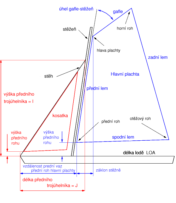
Figure 1. Sailcut plan definition
Obr 1. Definice
---------------------------------
3.1.2. Sail identifier
3.1.2. Oznaceni plachty
You enter there a text describing the sail you are working on (maximum 40 characters spaces included).
Plachtu na ktere pracujete muzete popsat textovym retezcem o maximalni delce 40 znaku (vcetne mezer).
-------------------------
3.1.3. Sail dimensions
3.1.3. Rozmery plachty
This is where the dimensions of the sail are entered.
Zde se vkladaji rozmery plachty. [IMHO je ta veta zbytecna...]
On a main sail the minimum value for the gaff length (headboard) is constrained to 5 mm. Value smaller than that will default back to 5 mm. The gaff angle is constrained to 90 degrees maximum between the gaff and the luff.
Pro hlavni plachtu (i trojuhelnikovou) je minimalni delka gafle 5mm. Mensi hodnota se prepise zpet ma 5mm. Uhel gafle-stezen je omezen na max. 90 stupnu.
[oni pisou gafle-predni lem, ale je to to jedno a navic jsem do obrazku napsal stezen a nechce se mi to predelavat]
-------------------------------
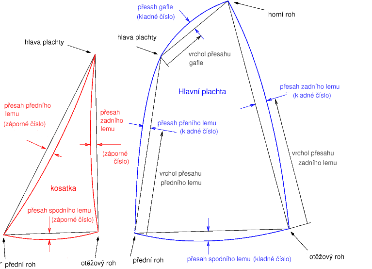
Positive round (roach) of the luff, foot, leech and gaff extend the sail outside of the straight edge line.
Negative round is equivalent to hollowing that edge of the sail.
Kladna hodnota presahu prednho, zadniho, spodniho lemu i gafle znamena, ze plachta presahuje nejkratsi spojnici prislusnych rohu.
Zaporna pak, ze plachta je "zahloubena" pod nejkratsi spojnici prislusnych rohu.
[prijde mi to lepsi nez hranu]
---------------------------------------------------------------------------
The position of the round or roach is expressed in percentage of the side length starting from the lower or most leftward end of that edge.
Vrchol presahu se udava v procentech delky hrany a pocita se od spodni, pripadne predni hrany.
Figure 2. Sailcut edges definition
Obr 2. Definice presahu a lemu
----------------------------
Dimensions and angles defining the sail plan are expressed in millimetre and degrees.
Length of the sail sides and diagonal are the 3D straight line distance between the corners of the sail.
Rozmery a uhly plachty jsou v milimetrech a stupnich.
Delka stran plachty a diagonala jsou 3D prime vzdalenosti mezi rohy.
-------------------------------
The actual length on the finished sail lais on the floor can be slightly longer depending on the shape of the sail. For example, the foot length entered in the screen below is 3600 mm. If the foot camber is null then that will be the actual distance between clew and tack (straight foot) of the finished sail. If a 10% camber is entered for the foot depth, then the actual foot will be the length of the arc which has 10% camber, that is 2.7% longer than the straight line foot length.
Delka hotove plachty ...lais on the floor... muze byt mirme vetsi v zavislosti na tvaru.
Napriklad delka spodniho lemu vlozena nize jest 3600mm. Jestlize vyklenuti/presah spodniho lemuje nula, pak je to prave delka plachty mezi spodnim a otezovym rohem hotove plachty. Ovsem, je-li vyklenuti/presah 10%, pak je skutecna delka vetsi o ono vyklenuti, coz je o 2,7% vice, nez prima vzdalenost rohu.
---------------------------
Having entered the sail main dimensions you can press on the Compute button to obtain additional informations on the sail, like the X-Y coordinates of the corners of the sail, the perpendicular length LP measured from the clew to the luff as well as IRC racing rules width.
Po zadani hlavnich rozmeru plachty muzete s tisknitim tlacitka "Prepocitat" obdrzet dalsi informace o plachte. Napriklad X-Y souradnice rohu, kolmou vzdalenost otezovy roh-predni lem, stejne jako IRC sirku. [nevim co znamena konec vety]
----------------------------------
The X-Y coordinates of the sail corners are usefull to quickly adjust the data entered. For example if you find that the clew height (Y) is way below or above the height of the tack when you would like it to be leveled, then you can substract or add the difference to the leech length.
X-Y souradnice rohu jsou uzitecne pro rychlou upravu vstupnich dat. Napriklad jestlize je otezovy roh pod prednim rohem (Y-souradnice) a chcete je srovnat do roviny, muzete jednoduse pricist rozdil k delce zadniho lemu.
---------------------------------
3.1.4. Layout
3.1.4. Strih
Click on the radio button corresponding to the desired layout of the sail. The layout of the panels does not affect the shape of the sail which is defined by its dimensions and its mould.
Volba radio buttonu odpovida zvolenemu strihu plachty. Strih a pocet pasu nema vliv na rozmer a tvar plachty, ktere byly zadany v sekci "Rozmery plachty" a "Tvar plachty".
----------------------------
Except for the Radial cut layout, the number of panels is determined by the cloth width and seam width entered in the Cloth box.
Vyjimkou je radialni strih, kde je pocet pasu a klinu zavisly na udajich v sekci "Material"
----------------------------
The most commonly used layout is the Crosscut. The panels are laid perpendicular to the straight line joining the peak to the clew of the sail.
Nejcasteji pouzivany strih je krizovy strih. Pasy jsou kolme na primku spojujici horni a otezovy roh plachty.
------------------------------
The Twist foot layout is similar to the cross cut except that the lower panels are rotated such that they do not intersect the foot of the sail.
"TEN" strih je podobny krizovemu strihu jen spodni pasy jsou pretoceny tak, aby nepotinaly spodni lem.
-----------------------
The Horizontal cut layout lay the seams in the horizontal plane. This option can be used to visualise the profile of the sail at various levels and to output files with the 3D coordinates of the sails for use by CFD tools.
Horizontalni strih ma vsechny svy vodorovne. To muze byt pouzito pri vizualizaci profilu plachty v ruznych urovnich a ve vystupnich souborech s 3D souradnicemi plachty. Pouziva se pro CFD nastroje.
---------------------
The Vertical cut layout places the panels parrallel to the straight line joining the peak to the clew of the sail. This is the favorite layout for the old timer's main sail.
Vertikalni strih umistuje pasy paralelne s primkou spojujici horni a otezovy roh. Je to preferovany strih pro hlavni plachty oldtimeru.
----------------------
The Mitre cut layout is the favorite for the old timer's genoa. The sail is divided in two parts by a line joining the clew to the mid point on the luff and the panels organised to be perpendicular to the foot in the lower part of the sail and perpendicular to the leech in its upper part.
Sikmy strih se pouziva pro genoy oltimeru. Plachta je rozdelena do dvou casti linii spojujici predni rod a stred zadniho lemu. Pasy jsou ve spodni casti kolme na spodni lem a v horni casti kolme na zadni lem.
-----------
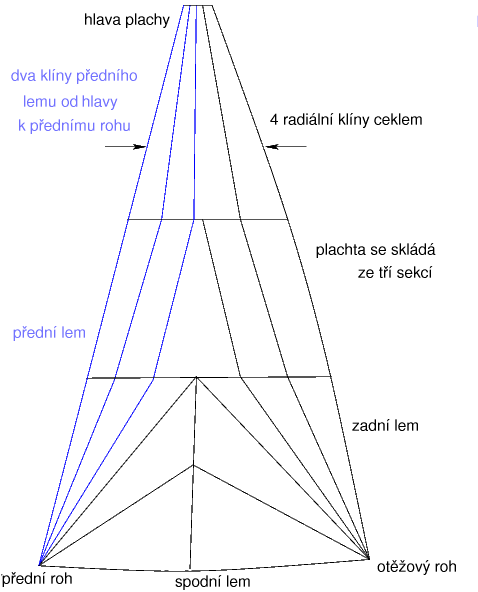
The Radial cut is used mostly for competition as the cloth is mostly aligned with the directions of maximum strain. When using the Radial cut option it is important to understand the definition of the number of sections, number of radial gores and number of luff gores (see Figure 3, Radial cut gores definition).
Radialni strih se pouziva hlavne pro zavodni plachty, kde je material maximalne namahan. Pouzijeteli radialni strih, je dulezite pochopit co znamena pocet pasu, pocet radialnich klinu a pocet klinu u predniho lemu. Viz obr 3.
Figure 3. Radial cut gores definition
Obr 3. Kliny radialniho strihu
-----------------------------
3.1.5. Sail shape
3.1.5. Profil plachty
You enter there the depth of the sail at 3 levels, near the foot, in the middle of the sail(the exact position being defined in the mould screen) and near the top of the sail.
Muzete zadat hloubku profilu ve trech mistech. Pobliz spodniho lemu, ve stredu a blizko vrcholu plachty. Presne souradnice jsou definovanu v okne "Tvar".
-----------------------
The twist angle is the angle expressed in degrees by which the top of the sail is rotated with respect to the foot. The twist is globally determined by the amount by which the apparent wind at the top of the mast is rotated with respect to the apparent wind at deck level. For a jib the twist is sometime driven by the need to have the upper part of the leech sufficiently open to clear the spreaders. For a mainsail the twist is also driven by the ability of the rig to carry the tension in the leech, in particular a gaff rig will have more twist in its main sail than a Bermuda rig. It is important that the twist angle entered in Sailcut reflects the reality of the shape of the leech when sailing in an average wind.
Uhel pretoceni je vyjadren ve stupnich. Je to uhel mezi spodnim lemem a vrcholem plachty. Pretoceni je urceno velikosti zdanliveho vetru na vrcholu stezne vztazeneho k vetru u paluby.
U kosatky je pretoceni urceno potrebou mit horni cast zadniho lemu dostatecne otevrenou pro ...to clear the spreaders.
Pretoceni hlavni plachty je take dano moznostmi takelaze nest napeti zadniho lemu. Specialne gaflova takelaz muze mit vetsi pretoceni, nez bermudska. Je zajimave, jak twist zadany v programu Sailcut CAD odrazi realitu tvaru zadniho lemu pri plachteni ve strednim vetru.
--------------
The sheeting angle value is the actual sheeting angle measured from the boat centerline when the sail is set on the boat. For a jib the minimum value is 5 degrees. The value is of importance to ensure that the sail is properly positioned when displayed in the rig viewer. You can then visualise for example the slot between a jib and the main sail as set on the boat.
Uhel plachty je uhel merenu od podelne osy lodi. Pro kosatku je minimalni hodnota pet stupnu. Cislo je dilezite pro nalezite umisteni pri porovnavani plachet v okne "Porovnani". Muzete tak napriklad modelovat sterbinu mezi kosatkou a hlavni plachtou.
-----------
3.1.6. Cloth
3.1.6. Material/Pas/panel...
Enter there the width of cloth used, the width of the seams between adjacent panels, the width of material to be added to the leech to make the leech hem and the width of material for the other edges hems.
Tady napiste sirku pouziteho materialu, sirku svu mezi sousednimi pasy, sirku pridavku na zadnim lemu a pridavek na ostatnich stranach (lemech).
-----------------------
Figure 4, Sailcut seams and hems definition describes the location of the various hems and seam width. Sailcut will compute the panels such that they fit within the declared cloth width including the seam and hems width as appropriate, except for a radial cut sail for which the width of each panels is computed from the number of radial panels entered.
Na obr 4, je vysvetleno kde se ktery lam nachazi, jakoz i cim se mysli sirka svu.
Sailcut pocita pasy tak...
Figure 4. Sailcut seams and hems definition
Figure 4. Svy a lemy
------------------------
3.2. Mould dialog screen
3.2. Okno Tvar
You can access the mould dialog from the Mould entry of the View menu.
Okno se otevre z hlavniho menu Navrh/Tvar.
-----------------
The depth and the shape of the sail can be entered at three levels located at the bottom (foot) the middle (sail's maximum depth height can be adjusted) and at the top of the sail.
Hloubka a tvar profilu plachty se definuje na trech mistech. V horni casti, ve stredu a u spodniho lemu plachty. (maximalni hloubka profilu muze byt nastavena)
---------------------------------
The position of the point of maximum depth of a profile is shown under the depth value. This position which depend of the luff and leech shape factors is expressed in relation to the cord of the profile. For exemple: 0.34 means that the point of maximum depth is at 34% of the local cord counting from the luff end of the profile
Misto maximalni hloubky profilu je zobrazovano v okenku "hloubka". Pozice je zavisla na nastaveni hodnot "Tvar predniho/zadniho lemu". Hodnota je vyjadrena relativne k "cord of the profile". Napriklad 0.34 znamena ze maximalni hloubka profilu je 34% z "the local cord counting from the luff end of the profile"
------------------------------
The luff shape and the leech shape can be adjusted for the Top profile and Middle profile only. The foot profile is always an arc of circle.
Tvar predniho i zadniho lemu lze nastavit pouze v hormi a stredni casti plachty. Spodni lem vzdy cast kruznice.
-----------------------
Under the luff shape factor, the corresponding value of the angle of entry of the profile is provided in degree. The angle under the leech shape factor is the exit angle of the profile. These angles are refered to the local cord and if you want to know for exemple the real entry angle of a profile with respect to the axis of the boat you have to add to the entry angle the twist at the level of the profile plus the sheeting angle.
The vertical position of the sail's maximum depth profile is controled by the vertical slide bar to the right of the left vertical frame.
Svisla pozice maximalni hloubky profilu je ovladana "vertical slide bar to the right of the left vertical frame."
---------------------------
In order to avoid that the leech makes a hook in the upper part of the sail when the wind increases, it is recommended that the Top profile luff shape value be higher than that of the middle profile and that the leech shape value at the top be lower than the middle value.
Abychom se vyhnuli tomu, ze zadni lem "makes a hook" v horni casti plachty kdyz vitr zesili, je treba, aby hodnota "Tvar predniho lemu" v horni casti byla vetsi nez ve stredni casti. Dale aby hodnota "Tvar zadniho lemu" v horni casti byla mensi nez ve stredni casti.
---------------------------
3.3. Rig viewer
3.3. Porovnani
This viewer is used to display several sails on the same rig. It is accessed via the Rig entry of the main screen's View menu.
V tomto okne muzete zobrazit nekolik plachet najednou. Je dostupne z menu Navrh/Porovnani
-----------
The New entry of the File menu is used to purge the viewer. ?????
-----------
The Add sail entry of the File menu is used to add sails already created and saved with Sailcut.
Volba pridat plachtu umoznije nacist novou(dalsi) plachto a pridad do okna k porovnami. Plachta musi byt predem vytvorena programem Saicut a ulozena.
-----------------
Once a sail is added to the rig viewer the sail information frame appears below and it is possible to translate the sail in the 3 directions by adding X-Y-Z displacement values. If you have misplaced a sail use the Reload button to recover the initial sail. You can also use the Remove button to eliminate a sail. 2 slides allows you to ratate the rig in azimuth and elevation and view the ig from any vantage point.
Jakmile je plachta pridana, informace (o ni) objevi se ve spodni casti okna. Nastavenim hodnot tam umistenych take muzete plachtu libovolne posouvat v 3D prostoru. Jestlize plachta vybehne v okna, tlacitkem Reload ji umistite na vychozi pozici. Tlacitkem "Odstranit" plachtu odeberete. Plachty se daji otacet dvema... [jak to rict] ...kolem dvou(obou) os.
------------------
The Save entry of the File menu is used to save a rig with a combination of sails.
Aktualni kombibaci plachet lze ulazit na disk - volba Ulozit.
-----------------
Rigs which have been saved can be later opened as an entity with the Open entry of the File menu.
Ulozenou kobinaci plachet lze opet nacist - vilba Otevrit. [kdo by to rekl...]
-----
Note that the rig viewer window must be closed to allow you to return to the main screen of Sailcut.
Pred navratem do hlavniho okna programu musi byt okno "Porovnani" zavreno.
----------------------------
3.4. View controls
3.4. Ovladani/manipulace se zobrazenou plachou
It is possible to zoom, pan and rotate the sail in the view window:
V okne je mozne plachtu otace kolem dvou os zvetsovat a zmensovat.
----------
Rotation : you can control the rotation that is applied to the sail by using the elevation and azimuth sliders located at the edges of the pane.
Otaceni: pouzit ovladace umistene pod a vlevo od okna.
---------------
Pan : click on a point with the left mouse to center the view on that point.
?????
----------------
Zoom : to zoom in press CTRL + and to zoom out press CTRL -. You can also use the zoom buttons in the view controls or your mouse wheel
Zvetsovani a zmensovani: CTRL+ zvetseni, CTRL- zmenseni. Take muzete pouzit tlacitka "Zvetsit" ,"Zmensit" v prave horni casti okna, nebo kolecko mysi.